×
模态框(Modal)标题
在这里添加一些文本
Close
Close
Submit
Cancel
Confirm
×
模态框(Modal)标题
×
ISSN 1000-0240
CN 62-1072/P
RSS
|
Email Alert
Toggle navigation
Home
About Journal
Editorial Board
Authors
Publication Ethics
Journal Online
Current Issue
Online First
Archive
Most Read
Most Download
Most Cited
Subscription
Advertisement
Contact Us
中文
Figure/Table detail
Propagation and fracture analysis of main control structural planes in dangerous rocks under water-ice phase transition
WANG Linfeng, XIE Mingjun, FU Yifan, HU Linyuan, TAN Xuanfang, RAN Jian
Journal of Glaciology and Geocryology
, 2025, 47(
4
): 990-1003. DOI:
10.7522/j.issn.1000-0240.2025.0079
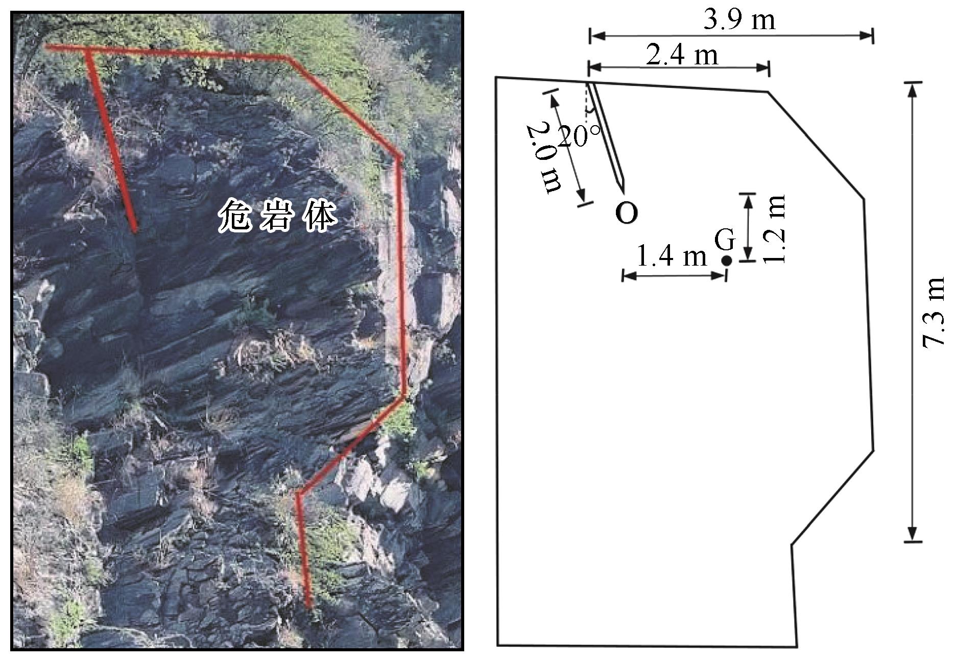
Fig. 5
Site photo (a) and planar model (b) of a dangerous rock in the study area
Other figure/table from this article
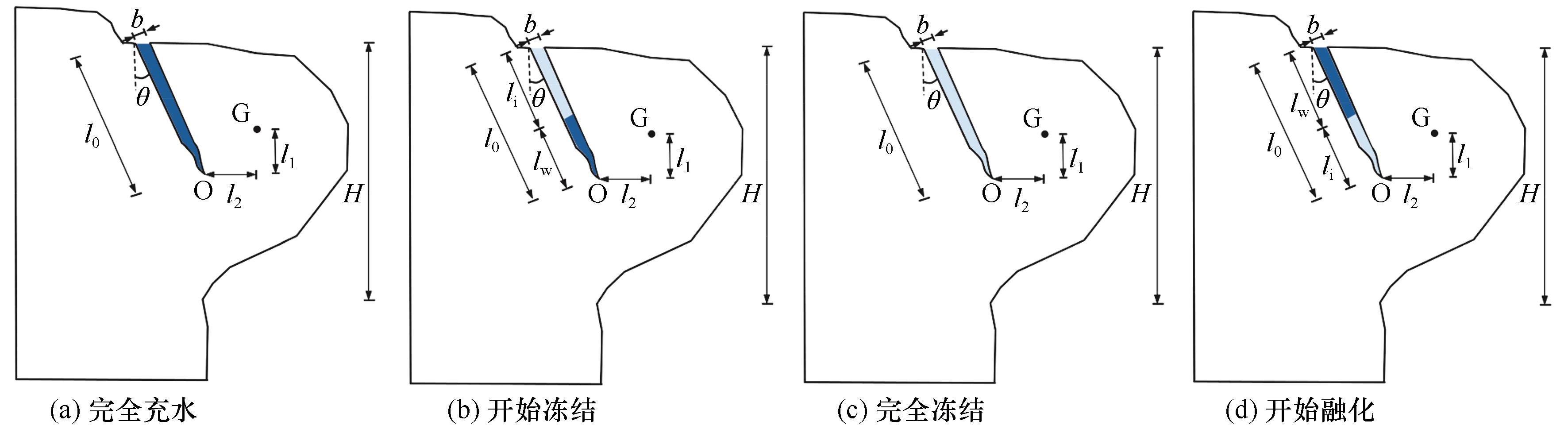
Fig. 1
Dangerous rock models with water at different stages of main control structural plane: (a) completely filled with water; (b) beginning to freeze; (c) completely filled with ice; (d) beginning to melt
Note:
H
: height of dangerous rock (m);
l
0
: initial length of main control structural plane (m);
b
: aperture of main control structural plane (m);
θ
: angle between structural plane and vertical direction (°);
l
1
,
l
2
: vertical and horizontal distance from point O at tip of main control structural plane to point G of center of gravity (m);
l
i
: ice-filled length within main control structural plane (m);
l
w
: water-filled length within main control structural plane (m).
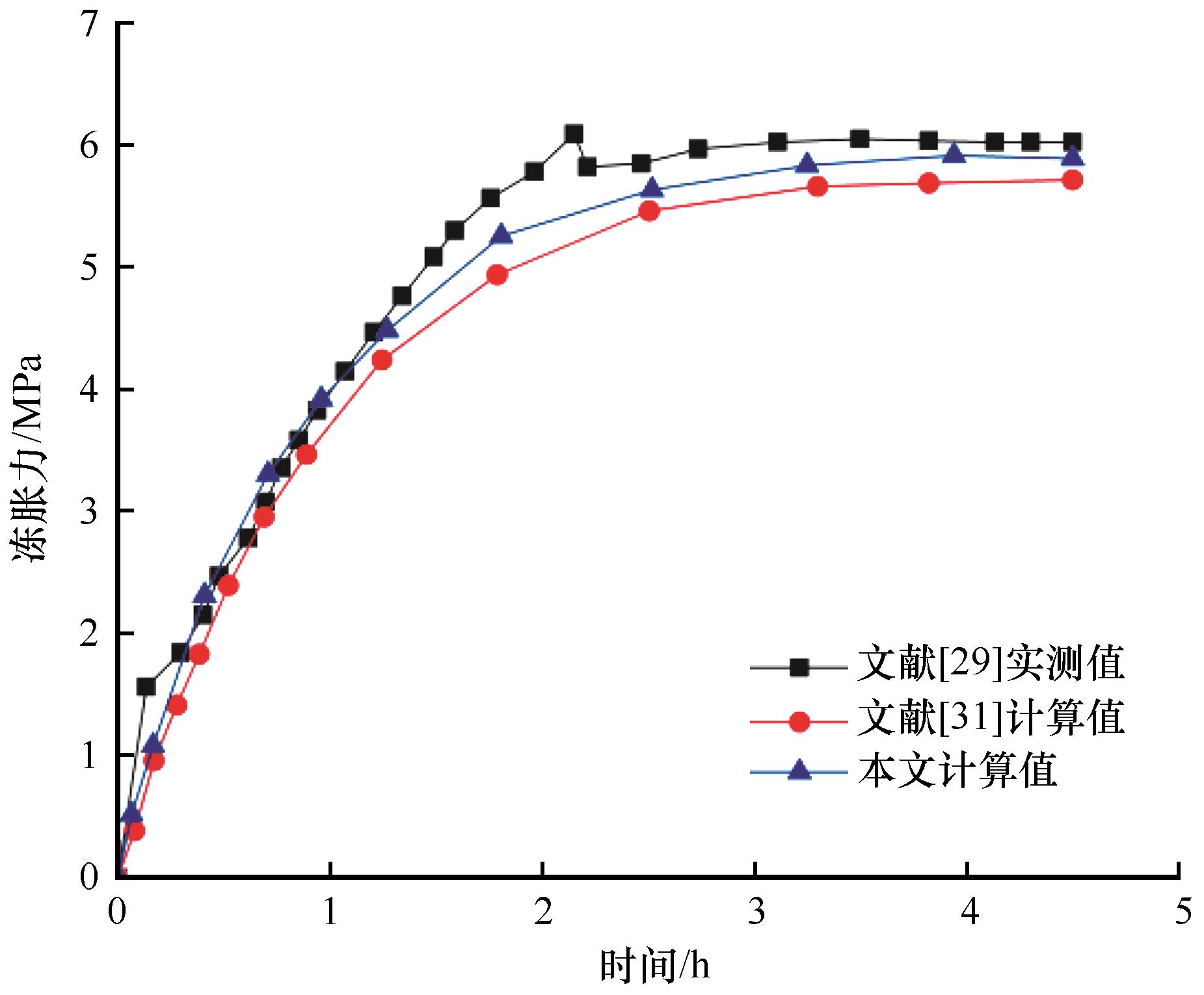
Fig. 2
Comparison of frost heave force results for limestone
Table 1
Calculation parameters
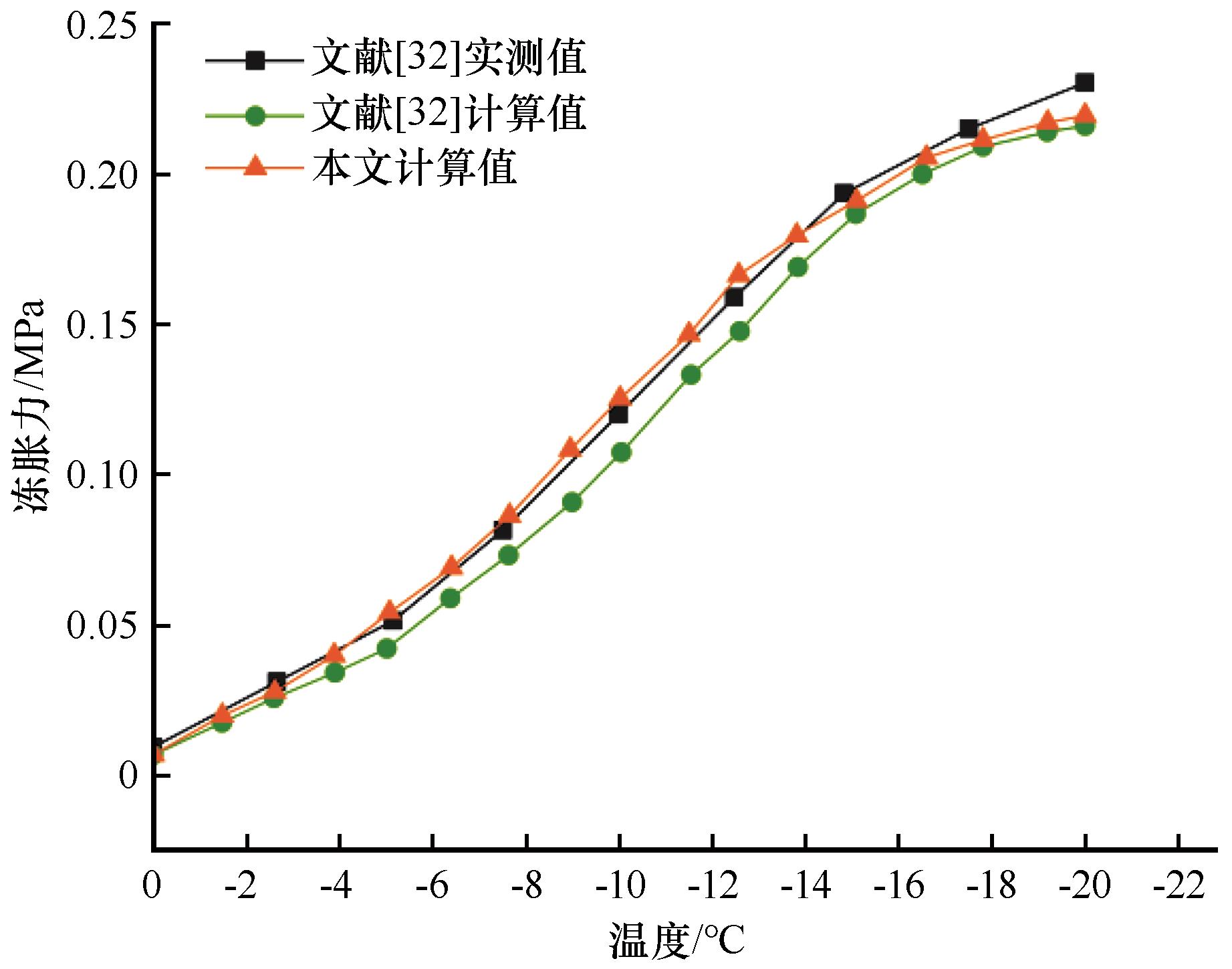
Fig. 3
Comparison of frost heave force results for slate
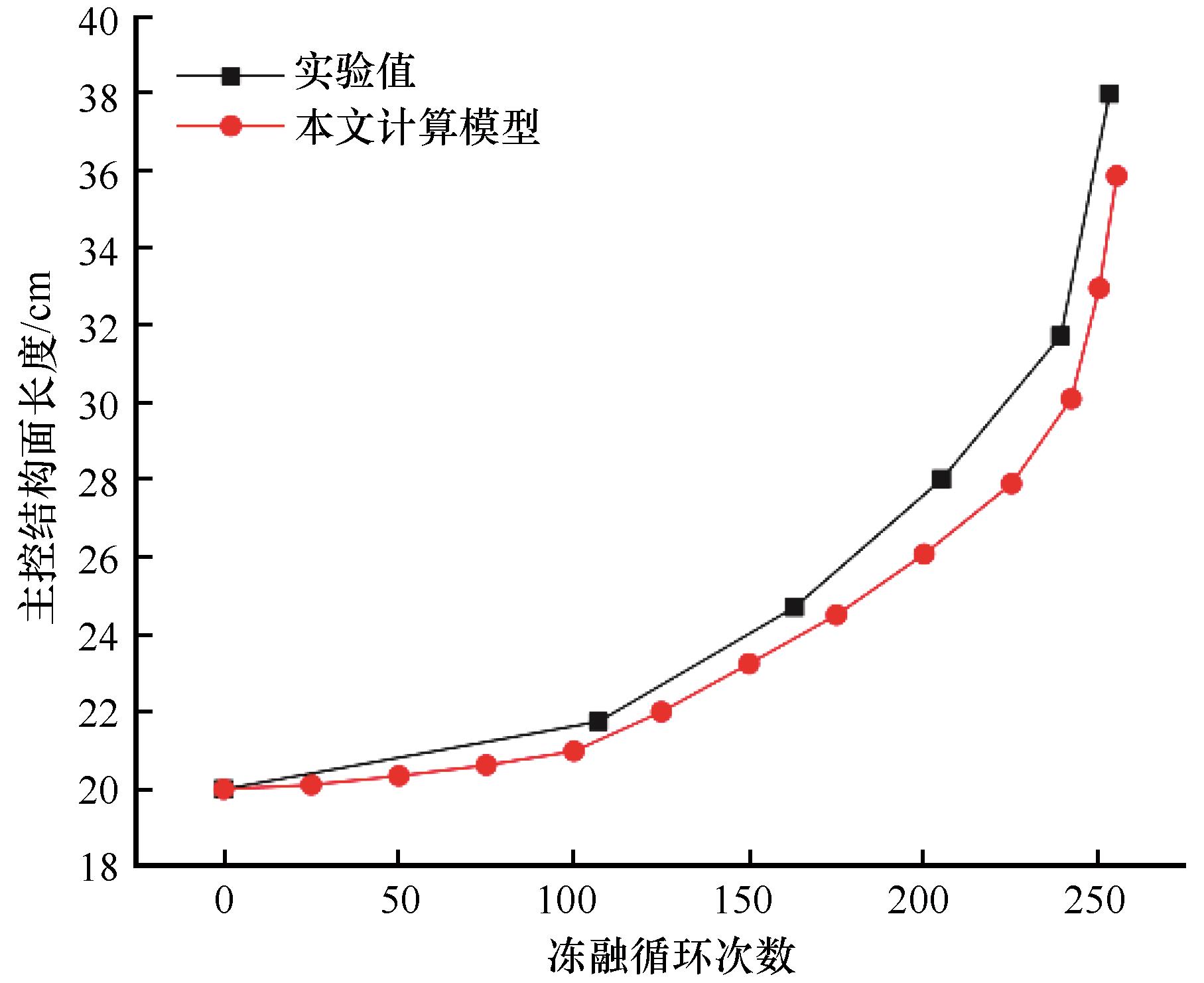
Fig. 4
Variation of length of main control structural plane with freeze-thaw cycles
Table 2
Temperature data of Barkam and statistics of freezing and non-freezing days
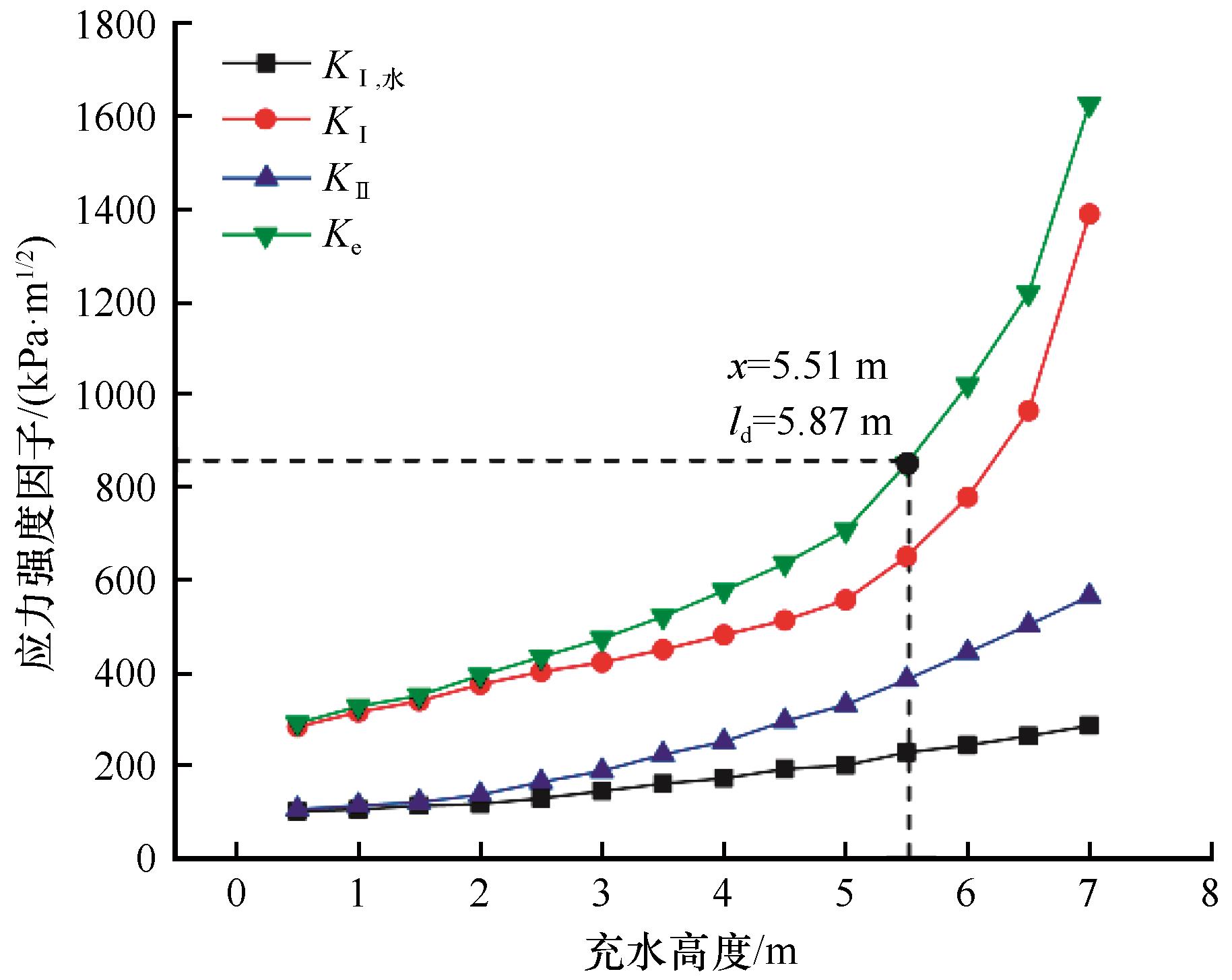
Fig. 6
Variation of stress intensity factor with water filling height
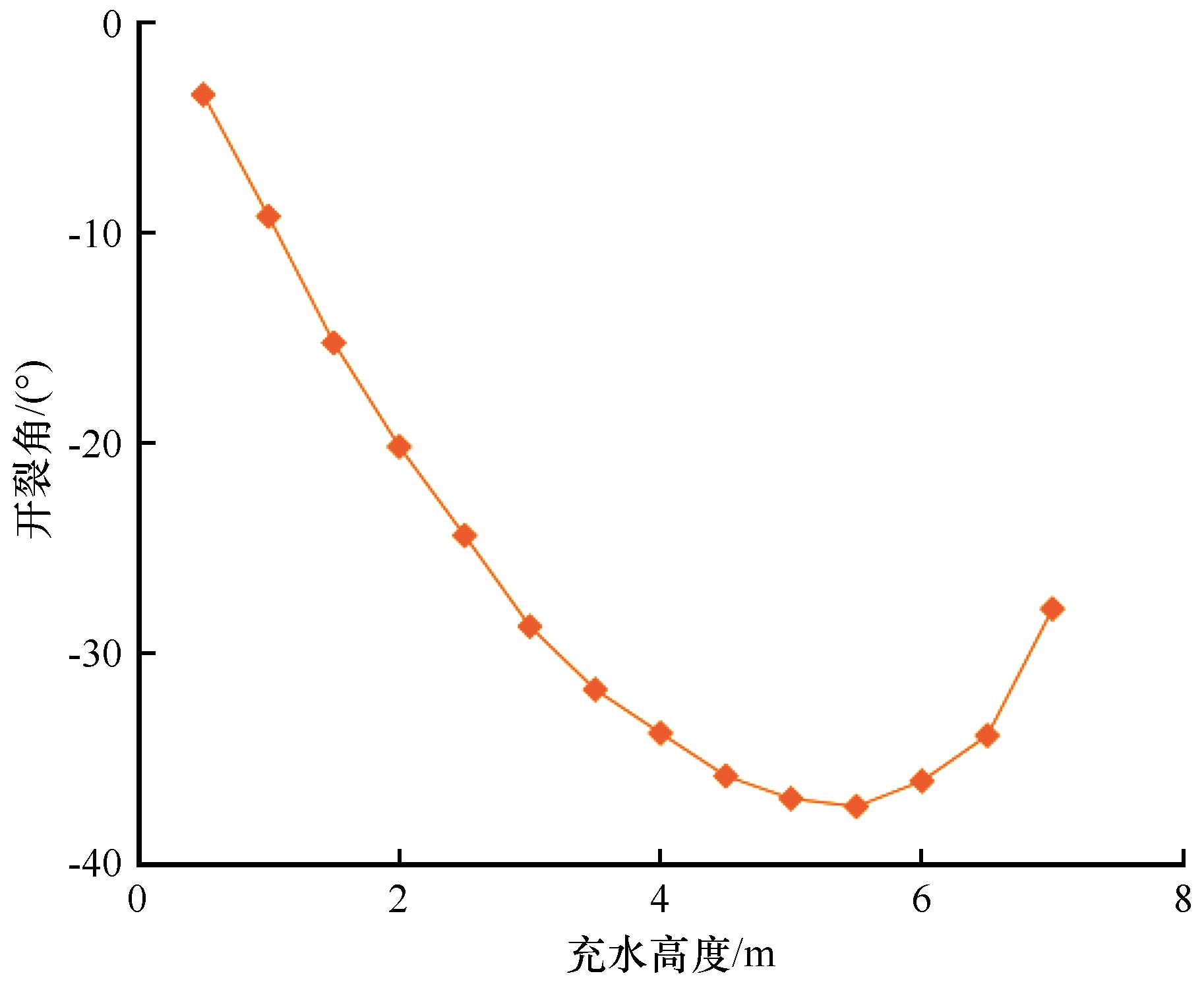
Fig. 7
Variation of cracking angle with water filling height
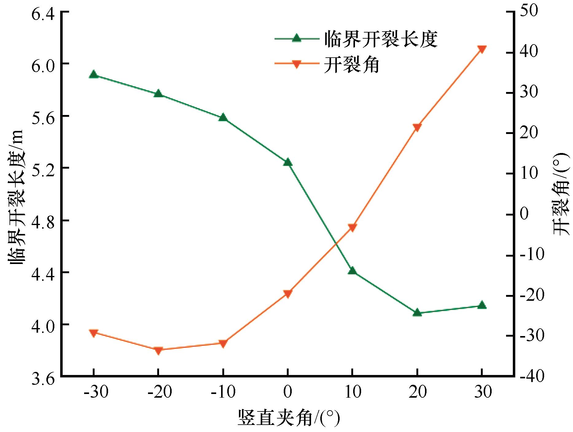
Fig. 8
Variation of critical cracking length and cracking angle with vertical angle
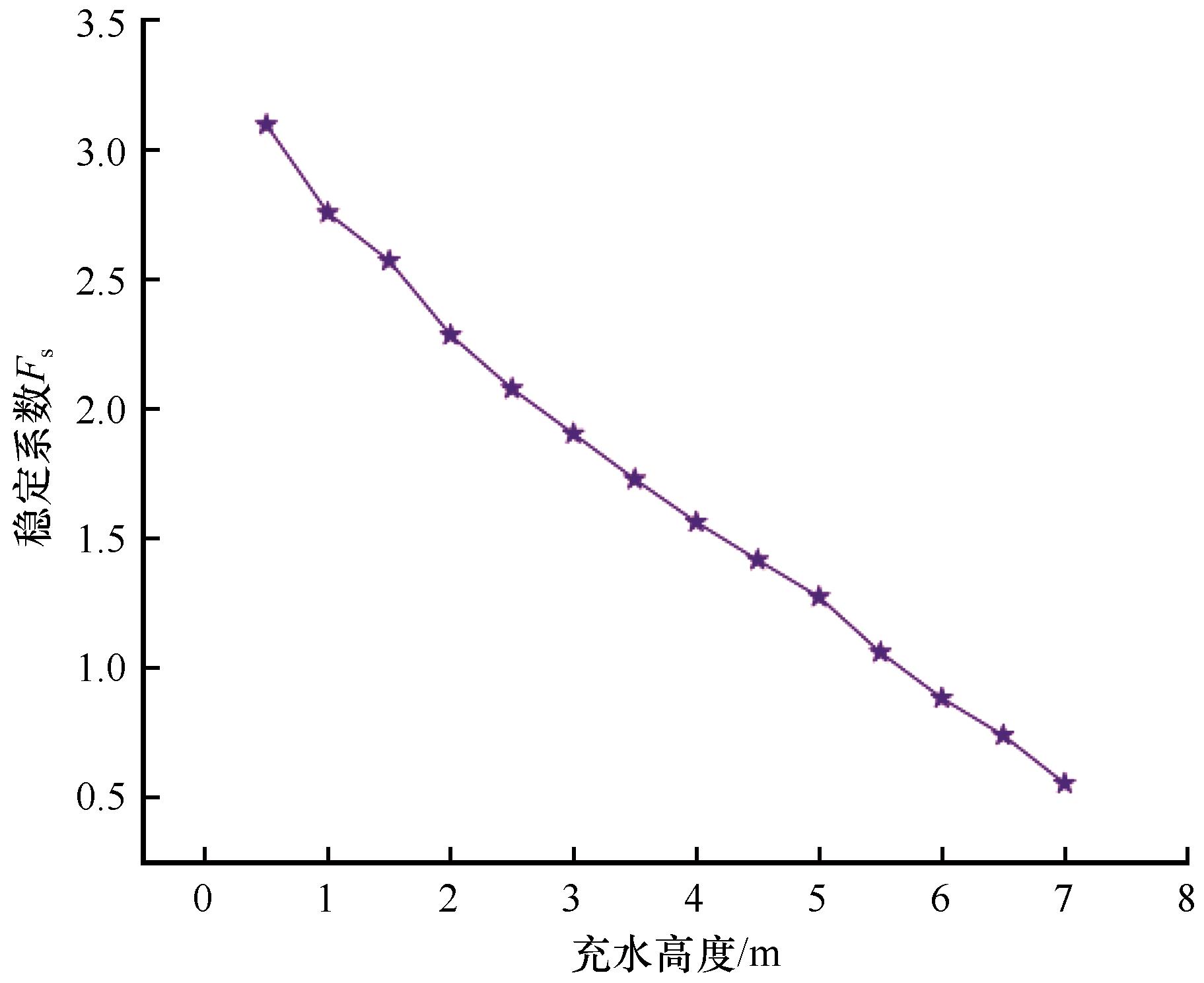
Fig. 9
Variation of stability coefficient
F
s
of dangerous rock with water filling height
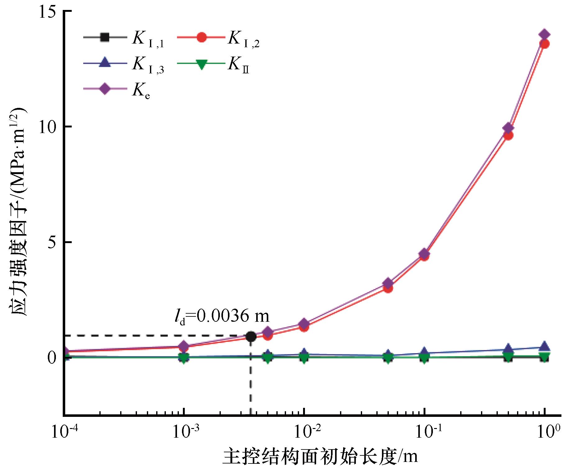
Fig. 10
Variation of stress intensity factor with initial length of main control structural plane
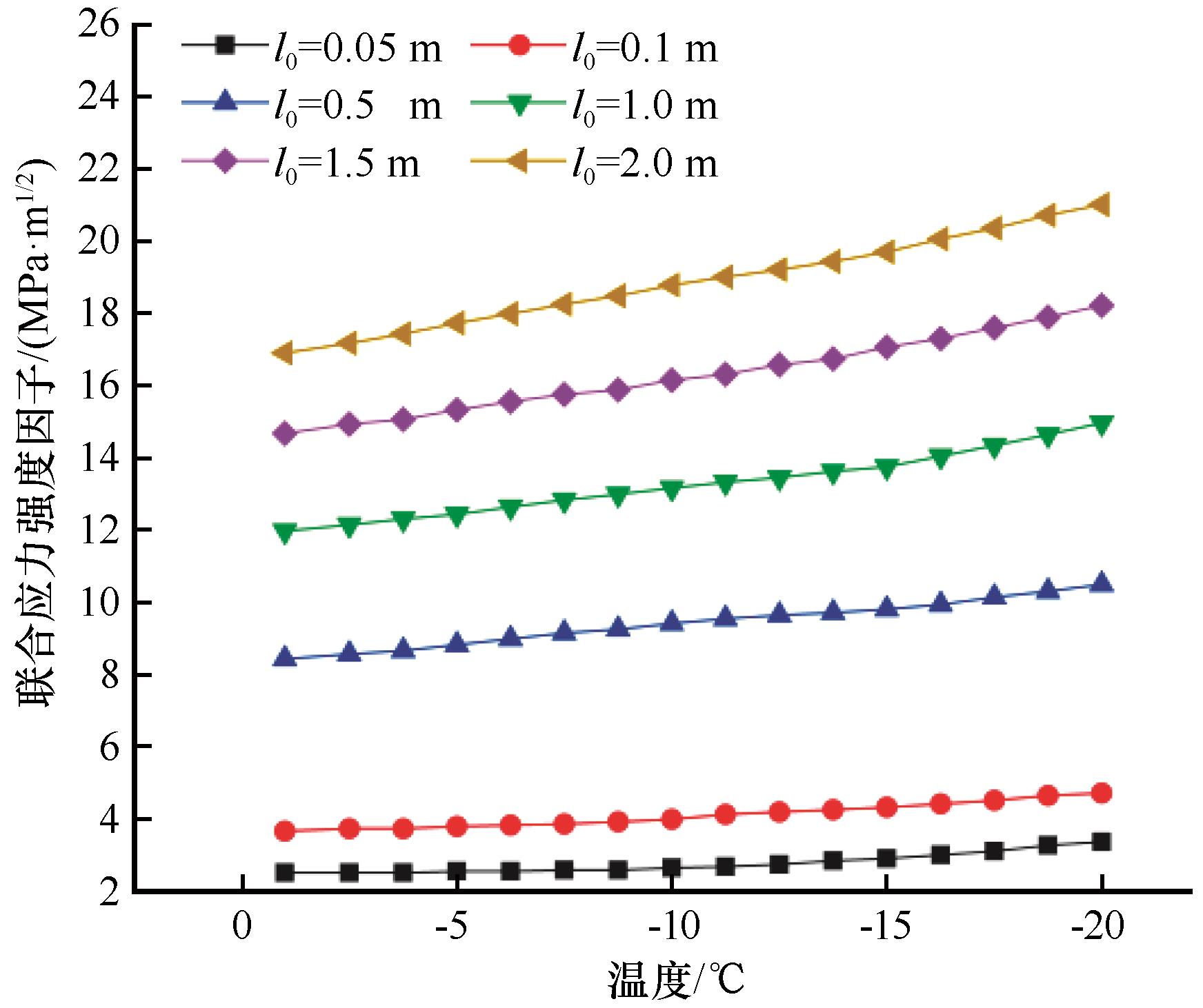
Fig. 11
Variation of joint stress intensity factor with temperature
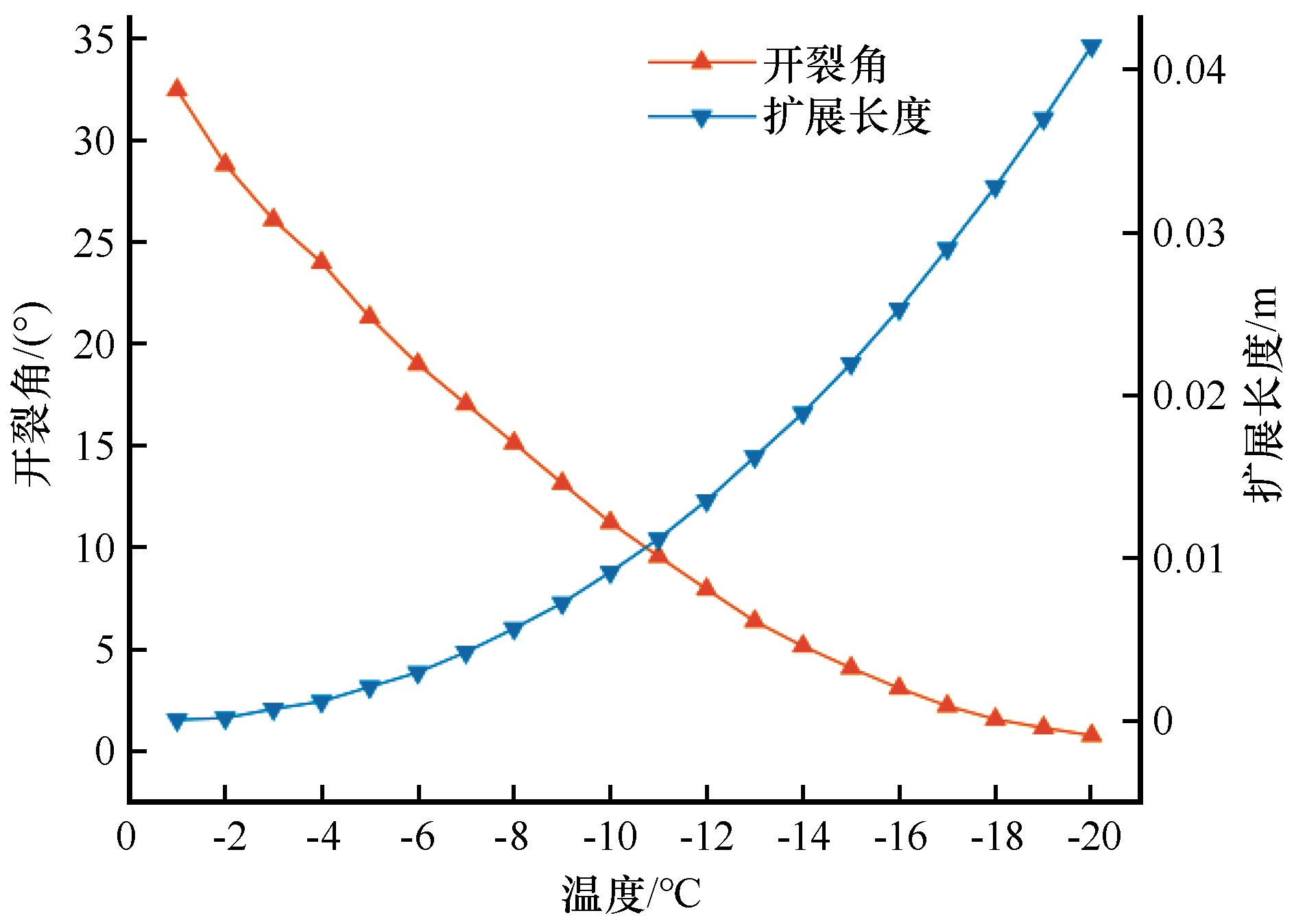
Fig. 12
Variation of cracking angle and propagation length with temperature
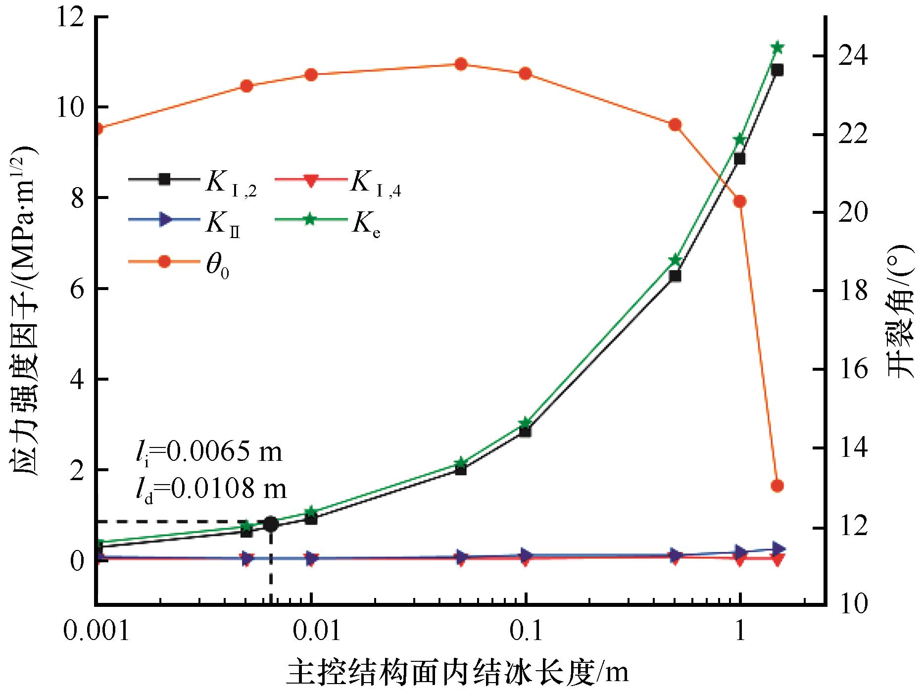
Fig. 13
Variation of stress intensity factor and cracking angle with freezing length
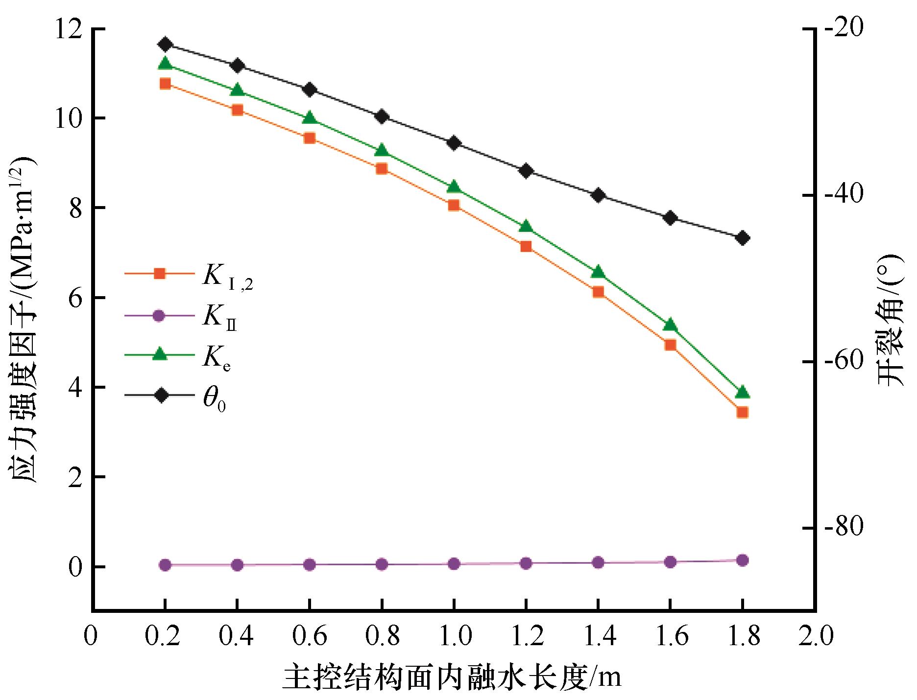
Fig. 14
Variation of stress intensity factor and cracking angle with length of melted water
Table 3
Propagation lengths of main control structural plane
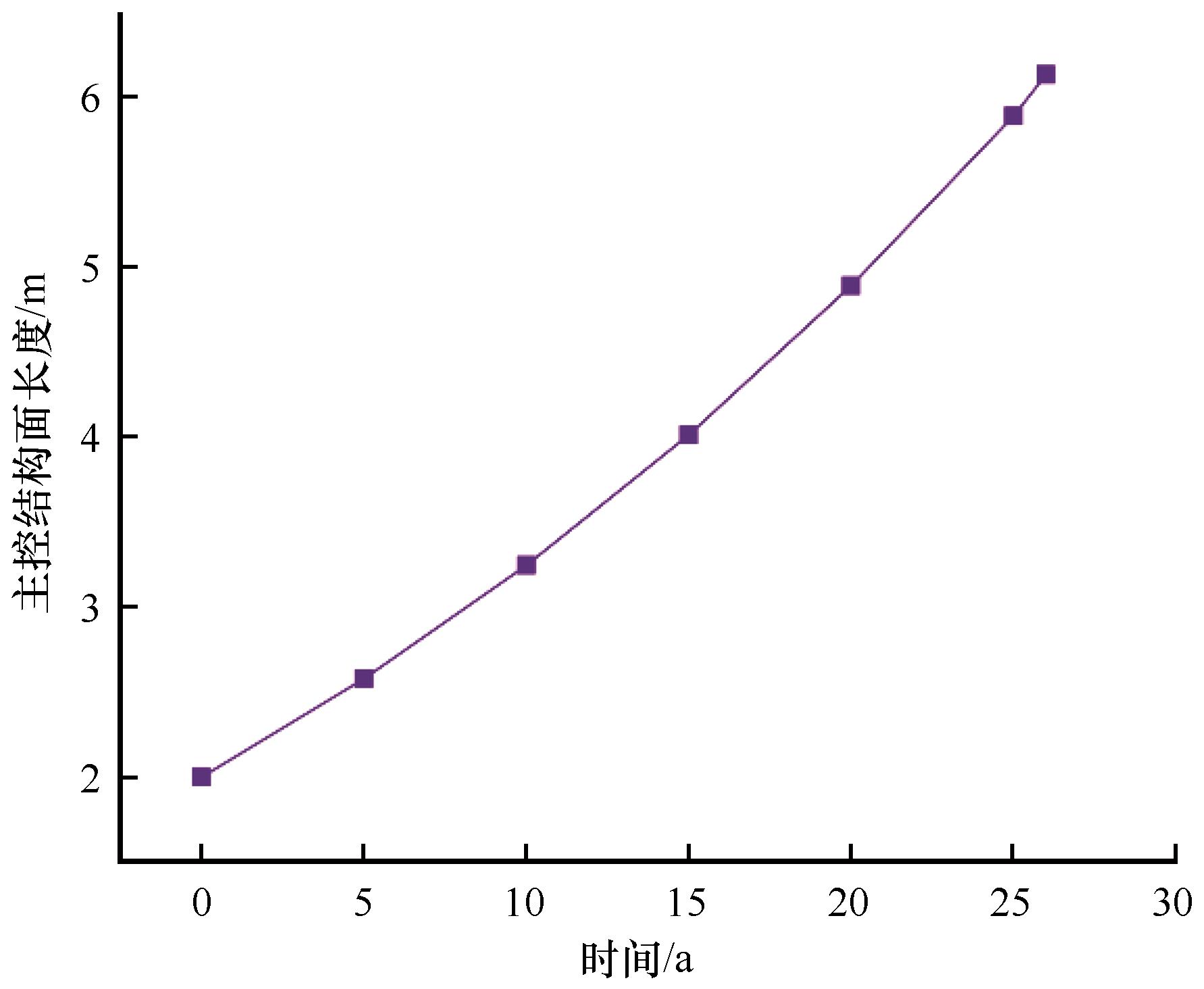
Fig. 15
Variation of length of main control structural plane with time